Nixie IN-9 kit assembly instructions
CAUTION: This device is a source of dangerous voltage! The Nixie kit must always be disconnected from the power and the output voltage dropped to a safe level, which should be confirmed by measurement. The completed kit should be housed in an insulating cover to avoid contact with high voltages.
Example Arduino Sketches
PWM Frequency Library
In your kit you will receive 31 components, this is to convert a 12v power supply to the necessary 150v required for driving the Nixie tubes and to allow the tube heights to be controlled using PWM inputs.
Upon opening the kit you should have this selection of components:

You can see on the PCB that next to each component footprint a letter and number is marked in gold, for example, R2, D1, and Q3. These markings tell you which component fits that hole. The list of components are:
R1 = R6 = R7 = 10 kΩ
R2 = 0.1 Ω
R3 = 1 kΩ
R4 = 510 kΩ
R5 = 4.3 kΩ
R8 = R9 = 220 Ω
C1 = 470 uF
C2 = C3 = C7 = C8 = 0.1 uF
C4 = 1 nF
C5 = 10 uF
L1 = 470 uH
SW1 = Push switch
Q1 = IRF640
Q2 = BC516
Q3 = Q4 = MJE340
D1 = SB140
D2 = UF4007
U1 = MC34063
LED = LED!
1x DC connector
2x screw terminals
1x 5 pin header
To ensure that the kit could fit on a nice small board the resistors have been designed to fit in a vertical configuration. This means instead of laying flat against the board the body of the resistor is vertical from the boards surface. To mount the resistor, bend one leg 180 degrees so that it runs parallel to the other leg. Then thread both legs through the PCB lining up the body of the resistor with the circle printed on the PCB. The solder into place and trim the legs.

To ensure you are using the correct components, make sure to carefully check them before soldering them into place.
Additionally, make sure to check the polarity for those components that require it; C1, C5, D1, D2 and LED. If you are not sure, you can check these pictures of an assembled board.
Start by soldering all the resistors to the board. Making sure to get R4 and R5 the correct way around!

With all the resistors soldered in place start adding the capacitors, starting with the ceramic capacitors.
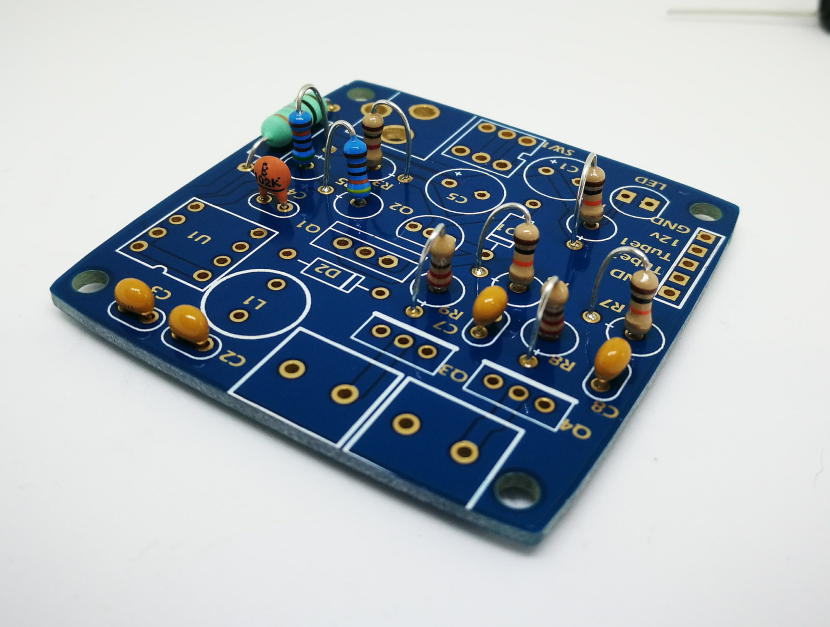
Next, add the aluminium electrolytic, making sure to match the polarity.

Now all the capacitors have been added we can start adding the silicon components starting with the diodes. To check which diode is which, the part number is printed on the side in small lettering.

Once you have identified D1, SB140, insert into board matching the diode stripe with that on the board. Repeat this for D2. Next, add Q2, BC516. Making sure to match the flat side of the transistor to that on the board.

Next, we can add the IRF640 MOSFET.

We are very nearly finished, with only a few components left to add. You can see above that the MC34063 has also been fitted, with the dot nearest the inductor. Now fit the remaining components Q3, Q4, LED, screw terminals, switch, DC jack and headers.
Your finished kit should look like this.

Check carefully that your kit looks like mine above if you are happy then you are ready to go ahead and test it.
The Nixie tubes will only work in one polarity, with the front of the tube upward from the table insert the legs and screw into place.

If you apply power at this point you will not see the tubes light up, however, there WILL be high voltage on your board, so you must be very careful not to touch the board.
In order to see the tubes glow you will need to connect an Arduino, microcontroller, Raspberry Pi etc to the Tube1 and Tube2 inputs on the PCB. A very simple test is to connect these to two Arduino pins, connect the ground pin to the ground on the Arduino and use digitalWrite to set them high. This will set both Tube1 and Tube2 to 5v, and the tubes will light up to their maximum height…
“Wait, I did that but the tube is only half lit!”

This is what you will most likely see. These tubes are Russian new old stock (NOS). That means they have been sitting in a box, for decades, unused. Worry not. Your tubes simply need to be “burnt in”. By driving the tubes at a maximum for about 30-60mins you will see over time the top of the orange glow creep up towards the top of the tube. Some will move faster than others, but they will get there, you might even need to leave it for a few hours. Once they have reached the top you will no longer need to burn them in and now whenever you use them they will reach their full height.
Once your tubes are burnt in, you are ready to try something more interesting. I have written a couple of example Arduino sketches to help you get going. You can download them here. When you look at these sketches you will see that I am not using the default PWM function, I am in fact using the PWM frequency library, the latest version of which you can download from here. This is for an important reason. Unlike an LED, which can react extremely quickly to changes, the Neon glow discharge inside a Nixie tube behaves quite differently. Making sudden changes can cause the bottom of the plasma to no longer be locked to the bottom of the tube, and instead, float in the middle. This is very undesirable. So in order to avoid this, the PWM signal is filtered before the controlling transistor. This low pass filter smooths the PWM signal but also limits how quickly changes to the tube height can be made. The standard Arduino PWM function uses a very slow frequency of 500Hz. Using a low pass filter for such a low frequency means it is also difficult to make quick changes to the tube height. For this reason, I have opted to use the PWM frequency library, this allows us to use a much higher PWM frequencies. I chose of 10kHz. Now our low pass filter can smooth the PWM signal and allow for quick tube changes.
If, however, you decide you really want to use the Arduino PWM functions then it is still possible. Though you might want to change the values of the low pass filters into the transistors, R6, C7 and R7, C8. By reducing the time constant, increasing the values of R and C, then this will filter the lower PWM frequency, but limit the speed at which tube changes can be made. If you will only ever make small changes, for example, driving a clock, then this might not be a problem. For more information on low pass filters see here.
Thanks and I hope you make something cool with your Nixie Bargraph Driver!
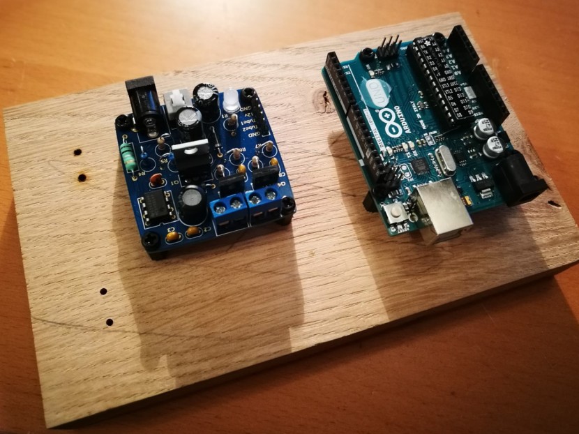
For those of you who backed for the full wooden clock kit, there are a couple of additional steps.
Once you have assembled the board and tested it with your nixie tubes you will want to mount them on the oak stand. The tubes are held in place with copper straps, however, these are slightly larger than the tube. So that the tubes stay in place the kit contains four rubber dots. A dot is to be placed between the two screw
The board and Arduino can be mounted to the back of the oak stand using the provided nylon standoffs screwed into the brass inserts in the oak. the board and Arduino should be mounted as such.
The tubes are held in place with copper straps, however, these are slightly larger than the tube. So that the tubes stay in place the kit contains four rubber dots. A dot is to be placed between the two screw holes and will press against the back of the tube. Applying just enough pressure to hold it in place. Attached the dot like in the picture.

Once attached you can then place the tube on top and screw the strap over the top. Once you have done this with both tubes you can then attach the wires. The wires thread through the two holes below the tube and can be attached to the PCB on the back.

I hope you like your new clock!
