IN-3 Nixie Matrix
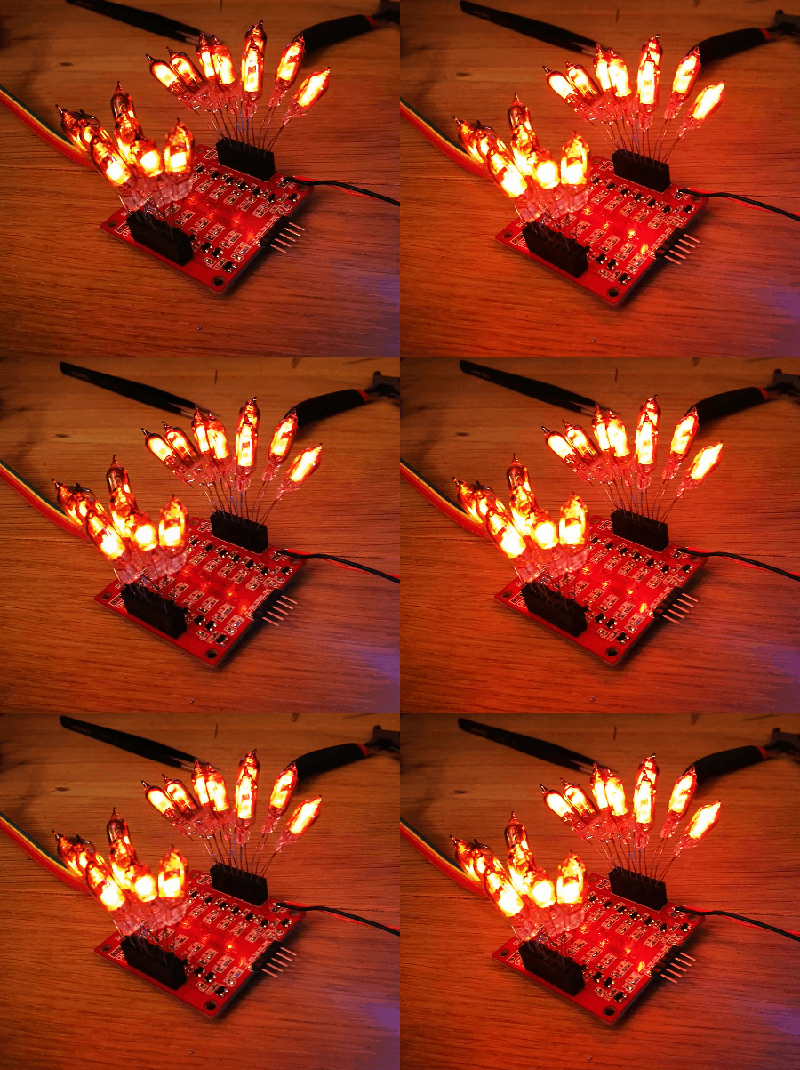
I recently bought a few (200) IN-3 nixie bulbs. Unlike the familiar numeric tubes or the bargraphs I’m fond of, these are just little bulbs. They have commonly been used as dots between digits in clocks and alike. Not content to make just another run of the mill Nixie project I decided to build a Nixie matrix, much like an LED matrix but with the lovely orange glow. My eventual aim is an 8×16 matrix, enough to display basic numbers and graphics. Though I’m starting with a simpler 4×4. This does provide the first challenge, how to drive so many tubes? The common way is multiplexing, however, since this is a one-off build and additional electronics isn’t too important (I’m not trying to optimise a BOM and a bit of extra work is fine) I have opted to directly drive each IN-3 tube. Not only drive each tube on and off but with a PWM signal. This should allow nice brightness variations and fading effects across the matrix. Pretty sexy. So now I just need 128 PWM channels… For ease I’ve gone for a 16 channel LED PWM driver (PCA9685). There’s even a nice Adafruit library for quick Arduino testing. It’s I2C so I intend the chain 8 of them together, these are driving mosfets that switch the high voltage tubes. (I’m also putting together an IN-9 driver kit (watch out Kickstarter…) so I have an abundance of high voltage supplies.)
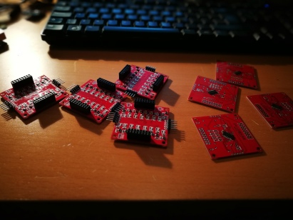
So far I’ve fully soldered up 4 boards and tested one with 16 tubes. All working nicely. Today I’ve cut out a small 4×4 MDF board to make up a little test board to get everything right before I go full scale. So far, it’s all be smooth sailing. Wonder how long that’ll last.


