Tagged: adafruit
IN-3 Matrix is nearly there
It’s been a long time since I wrote any updates about my IN-3 matrix project. Whilst I haven’t had much chance to work on it it has come a long long way from the original 4×4 tester.
I built an oak frame, machined an mdf board and attached 128 bulbs. Then I started the long process of wiring up each bulb to the PWM driver boards. In hindsight, I should have designed some kind of PCB strip to connect the bulbs to. This would have saved many hours of labour and been a lot neater. As it is each row of 16 bulbs takes about 1 hour to wire. Very boring so next time I know what to do!
I opted to buy a high(ish) voltage supply from eBay, the display can draw a lot of power when fully lit so despite having literally hundreds of high voltage driver boards for my IN-9 kit I figured to play it safe!
I am still only running some test code to make sure the bulbs light up and in the right order. I’m using an Arduino and the Adafruit Adafruit_PWMServoDriver library to communicate with the PCA9685 PWM drivers. Once I find a couple of hours to finish off the last two rows I’ll focus on what to use as a controller (probably the Teensy I’ve had laying about for 3 years) and actually write some proper firmware.
I’ve also now added a Github repo with all the hardware design files (DesignSpark PCB) for the driver boards and arduino sketches. I’ll continue to add to it as I progress.


Nixie Matrix prototype ready
It was a pretty straightforward task to assemble the bits into a functioning 4×4 nixie matrix. The tubes are mounted on spray painted black MDF with the PWM driver mounted on the back. They are each held in place with a small square of double sided foam tape. Wires soldered on the back to the tubes create a small nest and will be more neatly managed of the bigger version. I programmed an Arduino with the Adafruit pwmtest example and it all works fine. In fact, it works much better than I expected and I think I’m ready to go full scale, with no real modifications. All seems too easy.
I did a measurement of power consumption and the 4×4 uses a power of 1.8W, so will need about 15W for going full scale. Not too bad really for 128 tubes.

Running a PWM test.


IN-3 Nixie Matrix
I recently bought a few (200) IN-3 nixie bulbs. Unlike the familiar numeric tubes or the bargraphs I’m fond of, these are just little bulbs. They have commonly been used as dots between digits in clocks and alike. Not content to make just another run of the mill Nixie project I decided to build a Nixie matrix, much like an LED matrix but with the lovely orange glow. My eventual aim is an 8×16 matrix, enough to display basic numbers and graphics. Though I’m starting with a simpler 4×4. This does provide the first challenge, how to drive so many tubes? The common way is multiplexing, however, since this is a one-off build and additional electronics isn’t too important (I’m not trying to optimise a BOM and a bit of extra work is fine) I have opted to directly drive each IN-3 tube. Not only drive each tube on and off but with a PWM signal. This should allow nice brightness variations and fading effects across the matrix. Pretty sexy. So now I just need 128 PWM channels… For ease I’ve gone for a 16 channel LED PWM driver (PCA9685). There’s even a nice Adafruit library for quick Arduino testing. It’s I2C so I intend the chain 8 of them together, these are driving mosfets that switch the high voltage tubes. (I’m also putting together an IN-9 driver kit (watch out Kickstarter…) so I have an abundance of high voltage supplies.)
So far I’ve fully soldered up 4 boards and tested one with 16 tubes. All working nicely. Today I’ve cut out a small 4×4 MDF board to make up a little test board to get everything right before I go full scale. So far, it’s all be smooth sailing. Wonder how long that’ll last.


Dead bug LDC1000 inductance to digital shield
I needed to make a data logger to measure the inductance of a coil over time. The coil is flexible and so will distort while in operation. I wanted to know how much this would change the inductance in order to account for it.
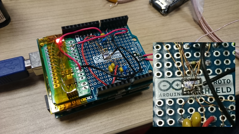
I found a nice IC from Texus Instruments, the LDC1000 inductance to digital converter. However it comes in an annoying SON-16 package, so time to whip out the fine tip soldering iron and practice my dead bug wiring. (For various reasons I thought logical at the time (though probably not) I opted not to use the handy eval board.)
So I superglued it onto an arduino protoshield, added a few caps and it was done. To measure the inductance the LDC1000 needs to be clocked, which is what the green board kapton taped to it is doing. This is a breakout I made for the Freescale/NXP KL03 cortex M0+, clocking the LDC1000 at 3MHz. You might ask why am I using the arduino for the logging and the KL03 to clock. Well. Whatever.
I plugged in an Adafruit datalogging shield and a few simple lines of code later I was logging inductance data. Sweet.